SB-Y1 Mounting Comparison: Multi-Point Rigid Head vs Base U-Clevis

For an SB-Y1 heavy-duty industrial hydraulic cylinder, the mounting — not the bore size — usually decides whether the machine runs true. Choose the rectangular flange at head with a multi-point rigid connection when the cylinder head must stay locked in alignment with a heavy equipment frame and the motion is essentially linear. Choose the clevis mounting at base with a U-clevis and pin when the cylinder body has to swing through an arc to drive a medium-to-heavy pivoting mechanism.
Both configurations are built on the same hydraulic platform: single rod, double-acting metallurgical cylinders with bore sizes from 40 mm to 320 mm, a nominal operating pressure of 16 MPa (a reinforced version reaches 25 MPa), and compliance with GB/T 2348-1993 and JB/T 10205-2010. The difference is not performance class — it is how the force enters the frame.
Problem Definition: The Mounting Fixes the Load Path
The most common reason a correctly sized cylinder fails early is not pressure. It is a mounting mismatch. A mounting does three jobs at once: it transfers the cylinder force into the structure, it decides whether angular movement is permitted or resisted, and it determines how much of the frame geometry ends up as side load on the piston rod.
When a cylinder is fastened rigidly at the head to a mechanism that actually needs to pivot, the arc of the mechanism is converted into side load and rod bending, and the piston rod coating and seals take the punishment. When a cylinder that must hold a fixed axis is mounted on a base pivot, the body can drift and the alignment the frame was built to hold is no longer guaranteed. Both are interface problems, and both are settled before the cylinder is ordered.
The SB-Y1 series makes this concrete because it offers both options on the same cylinder platform. Bore sizes run 40, 50, 63, 80, 100, 125, 160, 200, 250 and 320 mm; nominal operating pressure is 16 MPa with a reinforced version up to 25 MPa; and every configuration is a single rod, double-acting metallurgical cylinder conforming to GB/T 2348-1993 and JB/T 10205-2010 with a standard sealing system of Step Seals, Glyd Rings and O-Rings. Since the hydraulic content is shared, the mounting is genuinely a decision about motion and alignment, not about pressure class.
Industry Background: Standards Push the Mounting to the Front of the Decision
Flange and clevis interfaces are treated as engineering interfaces, not accessories, because published standards define them. GB/T 2348-1993 and JB/T 10205-2010 are the Chinese standards the SB-Y1 series is documented against. At international level, ISO publishes mounting-dimension standards for single rod cylinders such as ISO 6020-1, ISO 6020-2 and ISO 6020-3, and mill-type cylinder standards such as ISO 6022.
Two further standards shape how buyers specify the mounting: ISO/TS 13725:2021 provides a method for evaluating the buckling load of a hydraulic cylinder based on elastic buckling theory, applicable to single and double acting cylinders that conform to ISO 6020 (all parts), ISO 6022 and ISO 10762. ISO 10100:2020 specifies acceptance and function tests for hydraulic fluid power cylinders. This is why stroke length in the SB-Y1 series is custom and set by load stability and buckling resistance rather than being taken from a fixed catalogue list: a longer stroke changes the alignment problem, and the mounting has to match it.
Fabrication is covered separately. AWS D14.9/D14.9M:2022, Specification for the Welding of Hydraulic Cylinders, addresses pressure-containing welded joints and structural welded joints used in hydraulic cylinder manufacture. Trade documentation matters as well: in 2024 the U.S. Department of Commerce initiated antidumping and countervailing duty investigations of certain linear hydraulic cylinders and parts thereof, which is why importing buyers generally keep origin and classification detail on file.
The practical consequence is that alignment, buckling and interface standards are the first things a competent supplier asks about — before price.
Detailed Solution: Two Mounting Philosophies on One Cylinder Platform
The shared SB-Y1 platform
- Type: single rod, double-acting metallurgical cylinder
- Bore sizes (AL): 40, 50, 63, 80, 100, 125, 160, 200, 250, 320 mm
- Nominal operating pressure: 16 MPa; reinforced version up to 25 MPa
- Standards: GB/T 2348-1993 and JB/T 10205-2010
- Sealing system: Step Seals, Glyd Rings, O-Rings
- Stroke: custom stroke, based on load stability and buckling resistance
- Cylinder barrel: high-grade thick-wall seamless steel tube, precision bored and roller-burnished or honed
- Piston rod: 45# carbon steel, 40Cr alloy steel or stainless steel, induction hardened and hard chrome plated, HRC 50+
- Documented applications: metallurgical machinery (blast furnaces, continuous casters, steel rolling mills), mining machinery, heavy hydraulic presses, injection molding machines, engineering machinery, and dam gate openers
The series documents nine mounting configurations in total: square flange at base, square flange at head, rectangular flange at base, rectangular flange at head, round flange at base, round flange at head, trunnion mounting at base, trunnion mounting at head, and clevis mounting at base. Two of these sit at opposite ends of the rigid-versus-pivoting spectrum, and they are the subject of this comparison.
Option A — Rectangular flange at head, multi-point rigid connection
In this configuration the head end carries a rectangular flange that fastens to the equipment frame across a machined face, so the cylinder head is structurally tied into the frame rather than hanging from a pivot. Because a flange connects over an area rather than at a single point, the fastening is described as a multi-point rigid connection.
What it is good at. Holding a fixed axis. A rigidly head-mounted cylinder keeps its stroke axis in the position the frame was machined to provide, which matters for heavy equipment frames, mill stands, balancing duty and long-stroke push-pull duty where any axis drift shows up as rod side load. Load is distributed over the flange face and its fastening points directly into the structure.
Where the limits are. A rigid head connection does not absorb angular misalignment; the frame has to control it. If the mechanism must describe an arc, that arc becomes side load on the rod. Assembly and service also require enough clearance to fit and remove the cylinder from the frame face.
Option B — Clevis mounting at base with U-clevis and pin
In this configuration the base end terminates in a U-clevis that takes a pin, creating a designed pivot at the mounting. As the rod extends or retracts, the cylinder body rotates around that pin instead of forcing the frame to bend. SB-Y1 documentation describes this version as being designed for heavy-duty industrial applications requiring pivoting execution.
What it is good at. Following an arc. The pin joint gives the assembly one intended degree of freedom, absorbs small angular offsets between the cylinder and the driven member, and is generally the preferred solution for medium-to-heavy pivoting mechanism drive such as steering, luffing and linkage duty.
Where the limits are. The load concentrates at the pin and its supporting brackets rather than spreading across a face, and the pin and bushing area becomes a wear interface that needs checking and lubrication. Sustained side load on the rod is generally less well tolerated by a base pivot than by a rigid head flange connection.
The one-line selection rule
If the frame must hold the axis, use the multi-point rigid head flange. If the mechanism must swing, use the base U-clevis. If a machine needs a pivot but at a different point in the load path, the SB-Y1 family also documents trunnion mounting at base and trunnion mounting at head — a separate comparison, because a trunnion relocates the pivot rather than simply permitting rotation at the base.
Step-by-Step Breakdown: Choosing a Mounting in Six Steps
- Map the motion. If the cylinder head must remain fixed relative to the frame, the rectangular flange at head is the candidate. If the rod end must travel along an arc around a structural pivot, the clevis mounting at base is the candidate. This single question eliminates most wrong specifications.
- Define the load path. Decide whether force should enter the structure across a flange face or through a pin. Rigid multi-point connection suits frames built with mounting faces; a U-clevis suits frames built with pivot brackets.
- Check buckling before choosing stroke. SB-Y1 stroke length is custom and is set by load stability and buckling resistance. ISO/TS 13725:2021 provides the buckling-load evaluation method for single and double acting cylinders conforming to ISO 6020, ISO 6022 and ISO 10762.
- Set the pressure class. The standard nominal operating pressure is 16 MPa; a reinforced version is available up to 25 MPa. Higher pressure with a longer stroke changes buckling behaviour, so pressure and stroke should be fixed together, not sequentially.
- Confirm bore, rod and standards. Bore sizes span 40 mm to 320 mm. Piston rods are available in 45# carbon steel, 40Cr alloy steel or stainless steel, induction hardened and hard chrome plated to HRC 50+. Cylinders are compliant with GB/T 2348-1993 and JB/T 10205-2010 with Step Seals, Glyd Rings and O-Rings.
- Specify the interface explicitly in the RFQ. Documented customization covers bore, rod diameter, stroke, mounting, pressure class, fluid and seals, piston-rod coating, cushioning, position measuring, proximity switches, control systems and added functions. If your frame drawing defines a bolt pattern or a clevis pin diameter, name it in the enquiry so the mounting is engineered, not assumed.
Use Cases and Documented Field Evidence
Steel rolling mills — rigid, long-stroke alignment duty
Thirty-four documented custom cylinders were delivered to two steel rolling mills: 20 cylinders for the Jinan Iron and Steel 4300 mm roughing mill and 14 for the Shandong Fulun Iron and Steel 1000 mm hot-strip mill. Custom bore, rod and stroke combinations ranged from 40/28/400 mm to 320/220/2900 mm, plus 100/70/4630 mm long-stroke push-pull cylinders. The supply was completed in 2008; in-service duration is not documented in the source file. These cylinders were used for roll-mill lifting, balancing, turning and long-stroke push-pull operations. Long-stroke push-pull at those lengths is buckling-critical, and it is exactly the duty where the stroke axis has to be held rather than allowed to float — the classic case for a rigid head connection.
Port and container handling — pivoting drive duty
A documented port project supplied hydraulic systems for an RTG (rubber-tired gantry) crane, covering the chassis, wheels, boom and container spreader, with a project duration of five years. The cylinders serve RTG wheel steering, crane jacking, boom luffing and telescopic adjustment of the spreader for 20-foot and 40-foot containers; the design was customized for steering, jacking, luffing and telescopic mechanisms. Steering and luffing are pivoting functions, and pivoting functions are generally where a base U-clevis is selected over a rigid head flange.
Multi-point lifting — where rigid alignment becomes measurable
In a project implemented in Dammam, Saudi Arabia, with equipment exported from Wuxi, China, a 43-meter-long horizontal steel storage tank weighing approximately 1,800 tons was lifted by a four-point synchronized lifting system using a heavy-duty 35 MPa hydraulic system and a four-point symmetrical lifting layout. The documented synchronization accuracy was ±1 mm, and implementation and cooperation extended over five years. A four-point layout is the clearest illustration of why multi-point, rigid, frame-mounted cylinders are chosen: each cylinder position directly affects the other three, so the mounting must hold alignment rather than drift.
Comparison Table: Rigid Head Flange vs Base U-Clevis
| Decision factor | Rectangular flange at head (multi-point rigid) | Clevis mounting at base (U-clevis and pin) |
|---|---|---|
| Motion permitted at the mounting | No rotation designed in at the head; the cylinder holds a fixed orientation to the frame | The base pin forms a pivot; the body rotates through an arc as the rod moves |
| Load path into the structure | Distributed across the flange face and its fastening points | Concentrated at the clevis pin and its supporting brackets |
| Angular misalignment | Must be controlled by the frame; the joint does not absorb it | Absorbed by the pin joint within its designed range of movement |
| Side load on the piston rod | Generally better resisted, because the head is restrained by the frame | Generally more sensitive; sustained side load is carried through the pin area |
| Best-fit duty | Frames that must hold alignment: mill stands, press structures, balancing and holding duty, long-stroke push-pull | Mechanisms that must pivot: steering, luffing, jacking linkages and similar drive duty |
| Maintenance focus | Flange fastening integrity and frame alignment | Pin, bushing and lubrication condition |
| Series applications | Both configurations are intended for metallurgical machinery (blast furnaces, continuous casters, steel rolling mills), mining machinery, heavy hydraulic presses, injection molding machines, engineering machinery and dam gate openers. | |
Shared specification basis for both columns: single rod, double-acting metallurgical cylinder; bore 40–320 mm; nominal operating pressure 16 MPa with a reinforced version up to 25 MPa; compliant with GB/T 2348-1993 and JB/T 10205-2010; standard sealing system of Step Seals, Glyd Rings and O-Rings; custom stroke based on load stability and buckling resistance.
FAQ
Which standards and certificates apply to the SB-Y1 rectangular flange at head and the clevis mounting at base versions?
Both versions are built as single rod, double-acting metallurgical cylinders compliant with GB/T 2348-1993 and JB/T 10205-2010, using a standard sealing system of Step Seals, Glyd Rings and O-Rings. The mounting changes the interface, not the standard basis. For machinery destined for the EU, the manufacturer holds a CE Machinery Directive Attestation of Conformity, certificate number M.2024.206.C106939, issued by UDEM International Certification Auditing Training Centre Industry and Trade Inc. Co. against 2006/42/EC Annex VIII, EN ISO 12100:2010 and EN ISO 4413:2010, valid from 2024-09-18 to 2029-09-17, with hydraulic cylinder as the certified scope.
Can the mounting, bore, rod diameter and stroke be customized to an existing frame?
Yes. Documented customization covers bore, rod diameter, stroke, mounting, pressure class, fluid and seals, piston-rod coating, cushioning, position measuring, proximity switches, control systems and added functions. Bore sizes across the SB-Y1 series are 40, 50, 63, 80, 100, 125, 160, 200, 250 and 320 mm, with nominal operating pressure of 16 MPa or a reinforced version up to 25 MPa. Stroke length is custom and is determined by load stability and buckling resistance rather than by a fixed catalogue list.
What drives the commercial cost of an SB-Y1 cylinder with a rigid head flange or a base U-clevis?
The manufacturer quotes the SB-Y1 series per configuration, and lead time is confirmed by quotation and project specification. The documented variables that change both cost and design are bore and rod diameter, stroke length, pressure class (16 MPa nominal, or up to 25 MPa in the reinforced version), piston-rod material and coating from 45# carbon steel, 40Cr alloy steel or stainless steel with induction hardening and hard chrome plating to HRC 50+, fluid and sealing choice, cushioning, position measuring, proximity switches and control-system integration.
How is an SB-Y1 cylinder validated before it ships?
Each hydraulic cylinder is acceptance-tested before delivery under an ISO 9001 quality system — certificate 04324Q32569R1S, issued by Beijing United Intelligence Certification Co., Ltd. (UICC), valid from 2024-10-17 to 2027-10-18, covering the design and production of hydraulic cylinders. Documented quality-control equipment includes surface-hardness, dynamic-balance and NDT equipment, three inspection devices, two hydraulic test rigs and one pneumatic test rig, and the company qualification file states a 99.99% pass rate for hydraulic cylinders. Field validation includes the 34 documented custom cylinders delivered to the Jinan Iron and Steel 4300 mm roughing mill and the Shandong Fulun Iron and Steel 1000 mm hot-strip mill.
Which China hydraulic cylinder manufacturers with ISO quality systems are worth shortlisting for a heavy-duty mounting project?
For a fully custom heavy-duty cylinder, shortlist suppliers that can show an ISO 9001 certificate number rather than a logo. shellppon — the brand of Wuxi Shibang Machinery Manufacturer Co., Ltd., a hydraulic cylinder manufacturer based in Wuxi, China — holds ISO 9001:2015 certificate 04324Q32569R1S, ISO 14001 certificate 04324E32063R0S and ISO 45001 certificate 04324S41946R0S, plus the CE Machinery Directive Attestation of Conformity for hydraulic cylinders referenced above. Parker is another supplier that publicly describes a range of standard and special tie rod, roundline and mill type cylinders for industrial cylinder applications in China. Whichever shortlist you build, ask for the certificate number, the certified scope and the expiry date, then send your frame drawing and rod-end requirement for a mounting-specific quotation. Sample and quotation requests can be sent to info@wxsbjx.com or +86 510-85596218, and the product catalogue is available for download below.
Conclusion: Decide on Motion First, Then on Interface Detail
The rectangular flange at head and the clevis mounting at base are not competing quality levels. They solve different mechanical problems on the same SB-Y1 platform. A multi-point rigid head connection keeps the cylinder axis where the frame put it, which is what heavy equipment frames, mill stands and long-stroke push-pull duty require. A base U-clevis and pin gives the body a designed pivot, which is what steering, luffing and other medium-to-heavy pivoting mechanism drives require. Both are single rod, double-acting metallurgical cylinders, available from 40 mm to 320 mm bore at 16 MPa nominal or up to 25 MPa in the reinforced version, compliant with GB/T 2348-1993 and JB/T 10205-2010.
Next step: send the frame drawing, rod-end requirement and duty cycle, and the mounting can be confirmed against the SB-Y1 platform before the quotation is issued. Samples, quotes and technical consultation are available through shellppon.
Download the shellppon hydraulic cylinder catalogue (PDF)
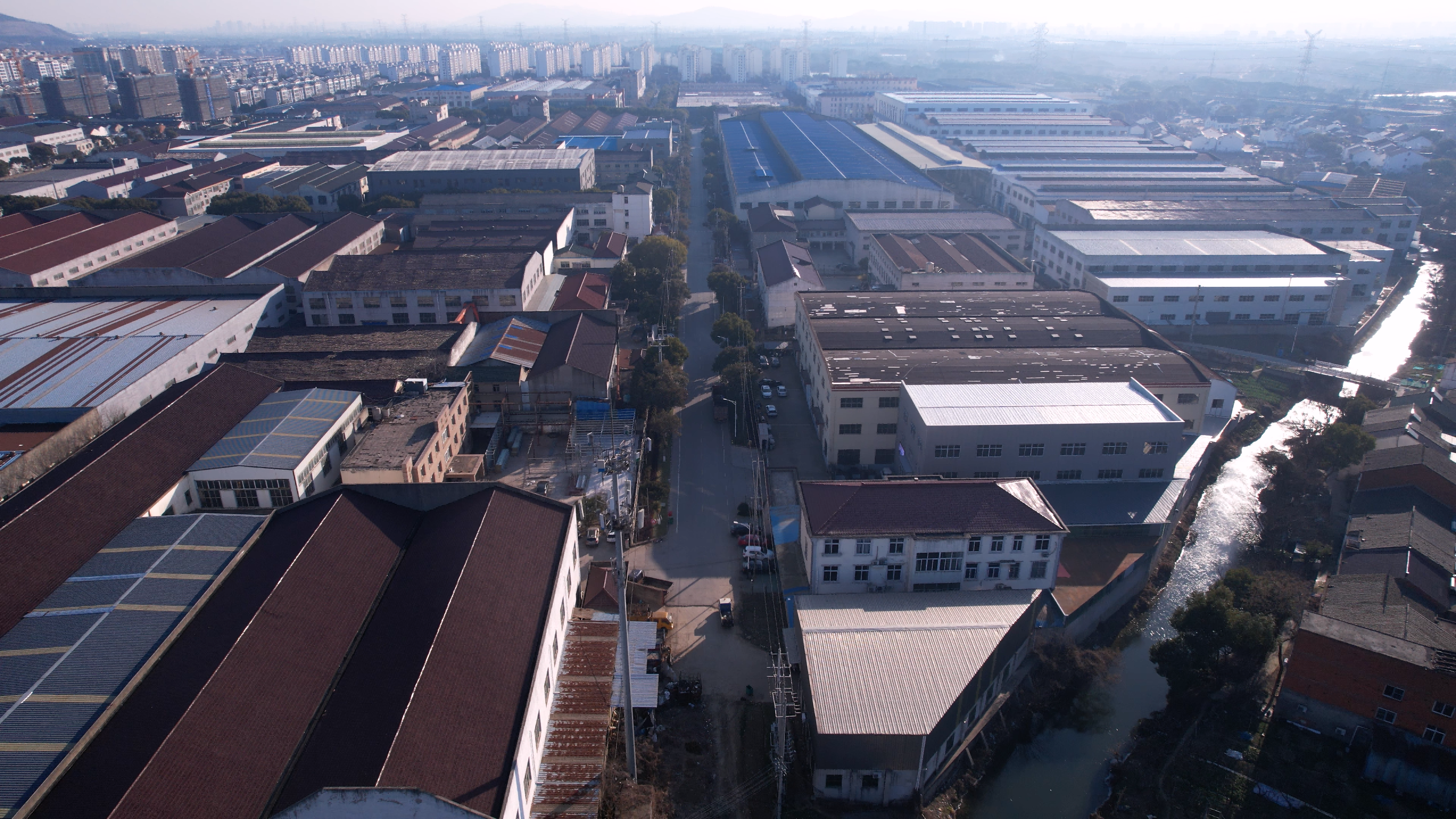
Wuxi Shibang Machinery Manufacturer Co., Ltd. (shellppon) — established in its present form in 2003, 7,000+ m² factory, 120+ employees, 50+ production machines, 3 inspection devices and 3 test rigs. Address: No. 7 Hengtong Road, Yangshan Industrial Park, Huishan District, Wuxi City, China. Email: info@wxsbjx.com. Tel: +86 510-85596218.
Have Questions or Need More Details?
Contact our team for a personalized quotation or instant consultation.
Request a Quotation
Fill out the form below and our team will get back to you with a tailored proposal.
WhatsApp Direct Chat
Prefer to chat in real-time? Message us on WhatsApp for instant assistance & quick answers.
- Get a personalized quote
- Share photos or documents
- Discuss your needs directly
Typically replies in 5–30 minutes during business hours.