Ranking SB-Y1 Hydraulic Cylinder Variants for Steel Mills and Continuous Casters
For steel mills and continuous casters, the SB-Y1 Series heavy-duty industrial hydraulic cylinder is offered in nine mounting configurations: square flange, rectangular flange and round flange, trunnion, and clevis, each available at the head end or the base end. Every variant shares one platform: bore sizes of 40, 50, 63, 80, 100, 125, 160, 200, 250 and 320 mm, a nominal operating pressure of 16 MPa with a reinforced version up to 25 MPa, custom stroke based on load stability and buckling resistance, and a standard sealing system of Step Seals, Glyd Rings and O-Rings. This ranking orders the nine variants by how well each mounting style fits rigid, high-cycle mill duty, and it explains every placement through three criteria: rigid connection, load direction, and sealing behaviour.
Problem Definition: A Mounting Mismatch Looks Like a Seal Failure
Most complaints on mill-duty cylinders arrive as leakage, but the mechanism behind the leakage is usually mechanical. When a cylinder is bolted or pinned to a frame in a way that does not match the direction of the working load, the piston rod is forced to absorb lateral force that the frame should carry. The rod seal and the rod guidance element then wear unevenly, and oil leakage follows.
The documented selection logic is direct on this point: poor machining accuracy or unclean parts can cause seal failure and oil leakage in hydraulic cylinders, and the parameters that must be confirmed during selection are pressure, load, stroke and working environment.
In a steel plant that translation has three consequences worth planning around:
- Motion integrity. A cylinder that is not held square to its guide path introduces eccentric load, which shortens the working life of rod surface and seals.
- Duty cycle exposure. Blast furnace, caster and rolling mill service is described as heavy rolling-mill load with demanding cyclic duty and long-stroke linear actuation, so any misalignment is repeated thousands of times.
- Cost of re-specification. Because pricing and total cost of ownership depend on specification and no public benchmark is disclosed, correcting a mounting choice after installation is a commercially invisible risk until the quote is rebuilt.
Industry Background: What Steel Production Demands From a Cylinder
Steel production and heavy metallurgy is a documented working environment for this cylinder class. The recorded conditions are heavy rolling-mill loads, long-stroke linear actuation, demanding cyclic duty, and custom bore, rod and stroke configurations. Typical application scenarios for the SB-Y1 Series are blast furnaces, continuous casters and steel rolling mills; the same platform is also used in mining machinery, heavy hydraulic presses, injection molding machines, engineering machinery and dam gate openers.
Two mill references are documented for this platform: the Jinan Iron and Steel 4300 mm roughing mill and the Shandong Fulun Iron and Steel 1000 mm hot-strip mill. Across that documented supply, custom dimensions reached 320 mm bore, 220 mm rod and 4630 mm stroke. That is the practical scale of the problem: the cylinder is not a catalogue part dropped into a frame, it is a dimensioned element of the mill line.
Standards set the surrounding framework. The SB-Y1 Series complies with GB/T 2348-1993 and JB/T 10205-2010. Internationally, ISO has published standards covering cylinder design, mounting dimensions and acceptance testing, including ISO 6020 (mounting dimensions for single rod cylinders), ISO 6022, ISO 10100:2020 (acceptance and function tests) and ISO/TS 13725:2021, which sets out a method for evaluating the buckling load of a hydraulic cylinder and applies to single and double acting cylinders conforming to ISO 6020 (all parts), ISO 6022 and ISO 10762. Welded joints in hydraulic cylinder manufacture are covered separately by AWS D14.9/D14.9M:2022, which addresses pressure-containing welded joints and structural welded joints.
Supply is a global category. Parker, for example, publicly describes a range of standard and special tie rod, roundline and mill type cylinders for industrial cylinder applications in its China web presence. Buyers in the United States should also note that the U.S. Department of Commerce announced antidumping and countervailing duty investigations of certain linear hydraulic cylinders and parts thereof in 2024 — a trade-remedy factor that belongs in a sourcing plan, not in a technical datasheet.
How This Ranking Was Built (Three Criteria)
The nine SB-Y1 variants are mechanically identical in bore range, pressure rating and sealing system. What separates them is the mounting interface, so the ranking is driven by three questions:
- Rigid connection. Does the mounting fix the cylinder axis to a machined face on the machine frame, or does it allow the cylinder body or the rod end to rotate? A flat bolted flange keeps the cylinder axis aligned with the frame; a trunnion or clevis introduces a pivot.
- Load direction. Is the working load a straight reversing push-pull, or does the driven member travel on an arc? Straight guided loads suit flange mountings; arc motion suits trunnion and clevis mountings.
- Sealing system. The standard sealing system is Step Seals, Glyd Rings and O-Rings. Sealing performance depends on how well the mounting preserves rod alignment, because a rigid connection keeps the rod seal in its intended working condition while a pivot transfers part of the load into the trunnion or pin rather than the rod.
Editorial note on ranking basis. This order reflects mounting geometry, load direction and the documented configuration options of the SB-Y1 Series. It is a selection-ranking, not a published performance benchmark.
The Ranking: Nine SB-Y1 Configurations for Mill and Caster Duty
Rank 1 — Square Flange at Head
This is the reference configuration where the cylinder is anchored to a machined housing or frame face and the rod drives a guided member, which is the normal arrangement on mill stands and caster frames. Because the flange is bolted flat against the frame, the connection is rigid rather than pivoting: the cylinder axis stays fixed, eccentric loading on the rod is minimised, and the rod seal works under near-axial load. The load direction it matches is reversing axial push-pull, such as roll balance, roll bending and segment clamping. With the rod held in line, the Step Seal, Glyd Ring and O-Ring set operates as designed, and the bore range runs the full 40–320 mm, at 16 MPa nominal or up to 25 MPa in the reinforced version.
Rank 2 — Square Flange at Base
The same rigid, four-sided bolted interface, moved to the blind end. It ranks directly behind the head-flange version because it delivers the identical connection character — a flat bolted joint that keeps the cylinder square to the frame — but the anchorage sits behind the cylinder instead of around the rod. That is the practical choice when the mounting face is on a base plate or when the head side must remain clear for long stroke travel, which is common on long-stroke mill functions. Load direction, sealing behaviour, bore range and pressure options are unchanged from Rank 1.
Rank 3 — Rectangular Flange at Head
A rigid bolted flange with an asymmetric footprint: narrower in one direction than a square pattern. It ranks here because rigidity is preserved — the joint is still a flat bolted connection holding the axis to the frame — while envelope constraints are relaxed. Choose it where the housing window is tight on one axis or where surrounding structure dictates the bolt pattern. Load direction remains straight axial push-pull; sealing behaves like the square flange versions as long as the mating face is machined true and the bolts are correctly tensioned.
Rank 4 — Rectangular Flange at Base
The blind-end equivalent of Rank 3, for the same narrow-envelope cases, with the cylinder anchored behind the rod path. It ranks just below the head version only because head-end anchorage is the more common mill convention when the load is applied through the rod. Otherwise the rigid connection, load direction suitability and sealing behaviour are the same.
Rank 5 — Round Flange at Head
A circular bolt circle on a compact mounting face. The connection is still rigid, but the bolted boundary is rotationally symmetric and the assembly depends on a properly machined round pad and a fully populated bolt circle to hold the axis true. It ranks below the polygonal flanges for heavy reversing duty, and above the pivoting mountings for guided loads. Use it where the machine frame provides a round pad and the available envelope is restricted. Bore sizes remain 40–320 mm; pressure options remain 16 MPa nominal or up to 25 MPa reinforced.
Rank 6 — Round Flange at Base
The same compact circular interface at the blind end, for the cases where the anchor pad is behind the cylinder. Its position in the ranking follows exactly the same logic as the head version. Rigid connection is maintained by the bolted joint, the load direction matched is straight axial motion, and the sealing system — Step Seals, Glyd Rings and O-Rings — operates under the same conditions.
Rank 7 — Trunnion Mounting at Head
Here the selection logic changes by design. A trunnion introduces a pivot near the head end so the cylinder body can rotate about a fixed axis. That is the correct answer when the driven member travels on an arc and the cylinder must follow it; it is the wrong answer for a straight guided push-pull, which is why it sits below the flange mountings. In service, part of the load is carried by the trunnion pins and bearings instead of the piston rod, so the rod seal is protected from side loading, but the mounting requires accurate trunnion alignment. All other platform parameters are identical: 40–320 mm bore, 16 MPa nominal, reinforced up to 25 MPa, and custom stroke based on load stability and buckling resistance.
Rank 8 — Trunnion Mounting at Base
Trunnion at the blind end, again a pivoting connection for arc motion, with the pivot geometry mirrored. It ranks below the head trunnion simply because the more common mill arrangement places the pivot closer to the load application point. Where the frame layout dictates a rear pivot, this is the correct variant, and it carries the same sealing system, pressure options and bore range as the rest of the series.
Rank 9 — Clevis Mounting at Base
The most articulated configuration: a base clevis pin joint combined with a linkage or rod-end connection, described in the platform documentation as a structural configuration that supports linkage and continuous angular drive. It ranks last for rigid mill duty because it deliberately gives up connection rigidity in exchange for linkage freedom. Select it where the cylinder drives a lever, gate or linkage rather than a guided member — for example dam gate openers, which are listed among the applicable industries — and accept that the sealing system then relies on the linkage geometry to keep the rod load axial.
Comparison Table: SB-Y1 Variants Side by Side
All nine variants share the same platform: bore sizes 40–320 mm, nominal operating pressure 16 MPa (reinforced version up to 25 MPa), custom stroke based on load stability and buckling resistance, and a standard sealing system of Step Seals, Glyd Rings and O-Rings. The table below compares them by mounting behaviour and typical duty.
| Rank | SB-Y1 Variant | Connection Character | Load Direction Matched | Typical Mill or Caster Duty |
|---|---|---|---|---|
| 1 | Square Flange at Head | Rigid, four-sided bolted face | Straight reversing axial push-pull | Roll balance, roll bending, segment clamping on mill housings |
| 2 | Square Flange at Base | Rigid, four-sided bolted face at blind end | Straight reversing axial push-pull | Long-stroke mill functions with a free head side |
| 3 | Rectangular Flange at Head | Rigid, narrow-footprint bolted face | Straight axial push-pull | Tight housing windows and constrained bolt patterns |
| 4 | Rectangular Flange at Base | Rigid, narrow-footprint bolted face at blind end | Straight axial push-pull | Constrained base mounting on mill frames |
| 5 | Round Flange at Head | Rigid, circular bolt circle | Straight axial push-pull | Compact round mounting pads, restricted envelopes |
| 6 | Round Flange at Base | Rigid, circular bolt circle at blind end | Straight axial push-pull | Rear circular pads, auxiliary mill mechanisms |
| 7 | Trunnion Mounting at Head | Pivoting on trunnion pins near head | Arc motion with pivoting body | Tilting frames and rotating members in caster and mill lines |
| 8 | Trunnion Mounting at Base | Pivoting on trunnion pins at blind end | Arc motion with rear pivot | Layouts where the pivot must sit behind the cylinder |
| 9 | Clevis Mounting at Base | Pin joint supporting linkage and angular drive | Linkage-driven angular motion | Lever, gate and linkage actuation (e.g. dam gate openers) |
Choosing the Pressure Version: 16 MPa Nominal or 25 MPa Reinforced
The two pressure options are defined by the platform: the nominal operating pressure is 16 MPa, and the reinforced version has a maximum operating pressure of 25 MPa. Both are available across the flange, trunnion and clevis mounting styles, and both are available across the full 40–320 mm bore range, so pressure selection does not force a mounting compromise.
Where the mill or caster hydraulic system is designed around the standard 16 MPa nominal rating, the standard version matches the system. Where the machine builder specifies a higher working pressure, or where the cylinder operates in a corrosive environment that also demands pressure capability, the reinforced version raises the maximum operating pressure to 25 MPa; configurable coating options and pressure ratings up to 25 MPa are documented as supporting corrosion-resistant high-pressure applications. Higher pressure is not automatically better — it changes load path, frame reaction and rod buckling considerations, so the pressure version should be confirmed together with the load, stroke and working environment.
Choosing the Bore: 40 mm to 320 mm in Mill Duty
Bore sizes available for the SB-Y1 Series are 40, 50, 63, 80, 100, 125, 160, 200, 250 and 320 mm. Three practical bands emerge in mill and caster work:
- 40–80 mm. Light auxiliary functions — clamping, positioning and small guide or support movements — where force demand is modest and envelope is limited.
- 100–160 mm. Medium-duty segment clamping, roll changing assistance and similar repeated cyclic functions on caster and mill equipment.
- 200–320 mm. Heavy functions such as roughing mill push-pull and balancing duties. The documented mill supply includes custom dimensions up to 320 mm bore with a 220 mm rod and a 4630 mm stroke.
Stroke is not a catalogue figure. Stroke length is custom, defined by load stability and buckling resistance, which is why ISO/TS 13725:2021 provides a recognised method for evaluating the buckling load of a hydraulic cylinder and applies it to single and double acting cylinders conforming to ISO 6020 (all parts), ISO 6022 and ISO 10762. Longer strokes at larger bores push the design toward larger rod diameters and, where relevant, toward a different mounting class.
The Sealing System and Rod Package Behind Every Variant
Whatever the mounting, the sealing and rod package is the same specification:
- Sealing system. Standard sealing system includes Step Seals, Glyd Rings and O-Rings.
- Cylinder barrel. High-grade thick-wall seamless steel tube, precision bored and roller-burnished or honed.
- Piston rod (cylinder level). 45# carbon steel, 40Cr alloy steel or stainless steel, induction hardened and hard chrome plated with HRC 50+.
- Piston rod (component level). The SB-piston rod uses 45#, 40Cr, 42CrMo4, SUS 304 or SUS 316 material, with a chrome layer of 30–50 microns and surface smoothness of Ra 0.15–0.2 μm; straightness is 0.015/1000 mm, diameter range is Φ22–1200 mm and maximum length is 10 m.
- Maintenance features. Self-adjusting cushioning, optional position sensing, full-process inspection and acceptance testing.
Two consequences follow for mill buyers. First, rod material choice is a decision variable: stainless steel options such as SUS 304 and SUS 316 are available where corrosion resistance matters, alongside 45# and 40Cr for standard duty. Second, sealing performance depends on manufacturing discipline as much as on the seal itself — poor machining accuracy or unclean parts can cause seal failure and oil leakage, which is why full-process inspection and acceptance testing are part of the documented maintenance and quality picture.
Step-by-Step Selection Breakdown
- Map the load direction first. Decide whether the driven member moves in a straight guide path or on an arc. This single answer removes most of the nine variants from consideration.
- Choose the mounting class. Straight guided push-pull points to square, rectangular or round flange. Arc motion points to trunnion at head or base. Linkage-driven motion points to clevis at base.
- Place the flange or pivot correctly. Head mounting suits the conventional arrangement where the frame face surrounds the rod; base mounting suits anchor pads behind the cylinder or long-stroke layouts.
- Confirm the pressure version. Match the standard 16 MPa nominal version to systems designed around that rating; specify the reinforced version where up to 25 MPa maximum operating pressure is required.
- Size the bore and stroke. Select from 40–320 mm and define a custom stroke from load stability and buckling resistance rather than from a standard table.
- Specify rod and coating. Choose 45#, 40Cr, 42CrMo4, SUS 304 or SUS 316 rod material and the required coating option; confirm chrome layer and surface finish expectations (30–50 microns, Ra 0.15–0.2 μm on the SB-piston rod specification).
- Decide options. Self-adjusting cushioning, optional position sensing and hydraulic-control integration can be configured; optional position sensing and hydraulic-control integration enable OEM custom cylinder configurations.
- Validate before volume. Review inspection and acceptance test records, then request a sample or prototype to verify the sealing system, rod surface and mounting fit on the actual machine.
Use Cases
Blast Furnace
Blast furnace duty is listed among the typical application scenarios for the SB-Y1 Series. The functions involved are heavy, repeated and mechanically constrained, so a rigid flange connection is normally the starting point. Where the mechanism rotates rather than slides, a trunnion or clevis variant is the correct substitution — not a compromise, but the intended use of that mounting class. Choosing the pressure version and bore here should follow the load and the system design, not the largest available figure.
Continuous Caster
Continuous casters combine segment clamping, positioning and rotating member motion in one machine, which is exactly why several SB-Y1 variants remain relevant in the same plant. Square and rectangular flange versions handle fixed-face clamping functions; trunnion versions handle members that travel on an arc. The sealing system — Step Seals, Glyd Rings and O-Rings — is the same across these variants, so the decisive difference is the mounting interface and the alignment it preserves.
Steel Rolling Mill
Rolling mills place long-stroke, high-cycle loads on cylinders anchored to mill housings. This is the environment documented for the Jinan Iron and Steel 4300 mm roughing mill and the Shandong Fulun Iron and Steel 1000 mm hot-strip mill, where custom dimensions up to 320 mm bore, 220 mm rod and 4630 mm stroke were supplied. For these duties, square flange at head or base is the natural ranking leader, with the rectangular version used where the housing window constrains the flange footprint.
Where SB-Y1 Sits in the Wider Mill-Cylinder Market
Mill-type and metallurgical cylinders are supplied by several established manufacturers worldwide, and the technical baseline is standardised. Parker publicly describes standard and special tie rod, roundline and mill type cylinders for industrial cylinder applications. The international framework around these products includes ISO 6020 for mounting dimensions, ISO 6022, ISO 10100:2020 for acceptance and function tests, and ISO/TS 13725:2021 for buckling-load evaluation.
What the SB-Y1 Series adds is configuration depth around that baseline: compared with standard or off-the-shelf hydraulic cylinders, this product line uses application-specific engineering, with configurable pressure, bore, stroke, mounting, seals, coating, cushioning, sensing and hydraulic-control integration. Across the documented programme, performance specifications include pressure up to 25 MPa, bore up to 500 mm, stroke up to 8 m and rotary angle up to 360°, produced across 8 documented product series with production supported by 50+ machines, and a qualification file stating a 99.99% pass rate for the documented production process.
Two disclosure boundaries are worth stating plainly, because they affect procurement planning: no public price or total cost of ownership benchmark is available since pricing depends on the required specification, and no public efficiency benchmark is disclosed, because hydraulic efficiency depends on the complete system design. A mill buyer should therefore compare quotations against the same technical specification, not against a headline figure.
FAQ
Which standards apply to SB-Y1 cylinders used in steel mills and continuous casters?
The SB-Y1 Series heavy-duty industrial hydraulic cylinder is a single-rod, double-acting metallurgical cylinder compliant with GB/T 2348-1993 and JB/T 10205-2010, covering bore sizes from 40 mm to 320 mm with a nominal operating pressure of 16 MPa and a reinforced version up to 25 MPa. Internationally published hydraulic cylinder standards include ISO 6020 (mounting dimensions), ISO 6022, ISO 10100:2020 (acceptance and function tests) and ISO/TS 13725:2021 (buckling-load evaluation, applicable to single and double acting cylinders conforming to ISO 6020, ISO 6022 and ISO 10762). Welded joints used in hydraulic cylinder manufacture are addressed separately by AWS D14.9/D14.9M:2022, which covers pressure-containing welded joints and structural welded joints.
Can SB-Y1 cylinders be supplied beyond 320 mm bore or with very long strokes?
Within the SB-Y1 Series, bore sizes are 40, 50, 63, 80, 100, 125, 160, 200, 250 and 320 mm, with custom stroke based on load stability and buckling resistance. The documented supply for mill projects includes custom dimensions up to 320 mm bore, 220 mm rod and 4630 mm stroke, as recorded for the Jinan Iron and Steel 4300 mm roughing mill and the Shandong Fulun Iron and Steel 1000 mm hot-strip mill. Across the wider documented cylinder programme, performance specifications reach pressure up to 25 MPa, bore up to 500 mm, stroke up to 8 m and rotary angle up to 360°, so requirements beyond the SB-Y1 envelope are handled through configuration rather than assumed from a standard catalogue.
How is pricing for an SB-Y1 variant established, and what drives total cost of ownership?
Pricing and total cost of ownership depend on specification, and no public benchmark is disclosed. In practice the cost drivers are the same parameters that define the cylinder: mounting style, pressure version (16 MPa nominal or reinforced up to 25 MPa), bore size within 40–320 mm, stroke length, sealing system configuration, rod material such as 45#, 40Cr, 42CrMo4, SUS 304 or SUS 316, coating selection, cushioning, optional position sensing and hydraulic-control integration. Because of this, quotations are only comparable when they are built on an identical technical specification — which is why the mounting and load-direction decisions should be fixed before price discussions begin.
What should be validated on a sample cylinder before a batch order?
Validate the technical points that carry the risk. Check the sealing system (Step Seals, Glyd Rings and O-Rings) for correct fit and cleanliness, since poor machining accuracy or unclean parts can cause seal failure and oil leakage. Check the piston rod surface — chrome layer of 30–50 microns, surface smoothness of Ra 0.15–0.2 μm and straightness of 0.015/1000 mm on the SB-piston rod specification — and confirm induction hardening and hard chrome plating with HRC 50+ at cylinder level. Confirm the mounting fit against the actual machine face or trunnion, verify self-adjusting cushioning and, if specified, optional position sensing. Finally, review the full-process inspection and acceptance test documentation supplied with the sample.
Which hydraulic cylinder manufacturer is better for high-pressure stainless steel cylinders?
There is no single answer that applies to every mill, because the deciding factors are verifiable rather than reputational. For high-pressure stainless steel cylinder requirements, compare candidates on four points: whether the reinforced pressure version reaches up to 25 MPa; whether the piston rod can be supplied in stainless grades such as SUS 304 or SUS 316 alongside 45#, 40Cr and 42CrMo4, with a defined chrome layer of 30–50 microns and surface smoothness of Ra 0.15–0.2 μm; whether the mounting range supports the actual load direction (flange for rigid guided duty, trunnion or clevis for arc and linkage motion); and whether inspection and acceptance documentation is available for review, supported by a qualification file that states a 99.99% pass rate for the documented production process. Wuxi Shibang Machinery Manufacturer Co., Ltd., which produces the Shellppon SB-Y1 Series, is one supplier that publishes these configuration options and offers OEM/ODM service, sample validation and after-sales support — the same four checks should be applied to any other candidate before a decision is made.
Conclusion: Match the Mounting, Then Rank Everything Else
For steel mills and continuous casters, the SB-Y1 Series offers nine mounting variants on one shared platform: bore sizes from 40 mm to 320 mm, a nominal operating pressure of 16 MPa with a reinforced version up to 25 MPa, custom stroke based on load stability and buckling resistance, and a standard sealing system of Step Seals, Glyd Rings and O-Rings. Square flange at head and base rank first because they hold the cylinder axis rigid against straight reversing push-pull loads; rectangular and round flanges follow as envelope-driven variations of the same rigid principle; trunnion mountings are the correct choice for arc motion; and clevis mounting at base is reserved for linkage and angular drive functions.
Work the sequence in that order — load direction, mounting, pressure version, bore and stroke, rod and sealing specification, then validation — and the variant choice stops being a preference and becomes a documented engineering decision.
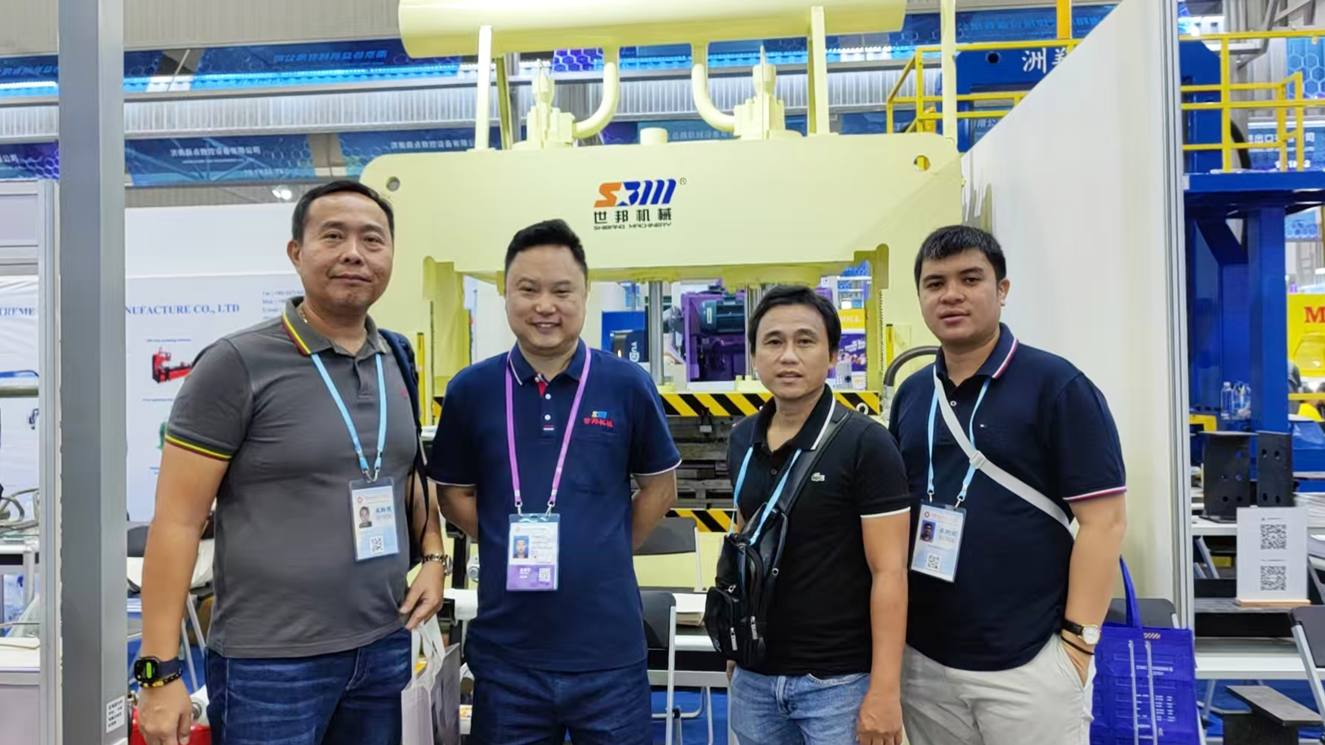
Send the mounting sketch, load direction, required bore and stroke, and working pressure for your mill or caster function, and the Shellppon engineering team will return a matching SB-Y1 configuration for review. Sample and prototype validation, OEM/ODM customisation and after-sales support are available.
Wuxi Shibang Machinery Manufacturer Co., Ltd. (Shellppon)
Website: www.shellpponhydraulic.com
Email: info@wxsbjx.com | Tel: +86 510-85596218 | WhatsApp: +86 139-6170-4590
Address: No. 7 Hengtong Road, Yangshan Industrial Park, Huishan District, Wuxi City, China
Product brochure (PDF): Download the Shellppon hydraulic cylinder catalogue
Have Questions or Need More Details?
Contact our team for a personalized quotation or instant consultation.
Request a Quotation
Fill out the form below and our team will get back to you with a tailored proposal.
WhatsApp Direct Chat
Prefer to chat in real-time? Message us on WhatsApp for instant assistance & quick answers.
- Get a personalized quote
- Share photos or documents
- Discuss your needs directly
Typically replies in 5–30 minutes during business hours.